Become a member
Take advantage of exclusive member benefits, world class events, networking and specialist support


 Become a member


 Autonomous mobile robots & Guides vehicles’
Advanced robotics
The basic structures of robots are defined by their core design and capabilities. Robots feature specific types of handling, lifting, placement and inspection functions with a range of capabilities in terms of precision, reach, flexibility and load.

Basic parts of a robot include hinged joints which allow movement in x, y and z planes, powered by electric motors.
When selecting a robot for a particular task, several decisions must be made. The first of these is the structure of the robot required. There are several different structures commonly available, and each has its own set of limitations and benefits.
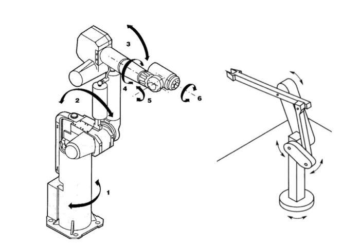
(Figure 1) Left: Jointed Arm Robot Structure, Right: with parallelogram between the shoulder and elbow joints. [5]
The jointed arm robot closely resembles the human arm. This structure is very flexible and can reach over obstructions. It can generally achieve any position and orientation within the working envelope in eight different ways.
This can cause control problems. When driving these robots in their natural coordinate system (joint space) the motion of the robot from one point to another can be difficult to visualise as the robot will move each joint through the minimum angle required.
This means that the motion of the tool will not be a straight line. This structure of robots is used for a wide range of applications including paint spraying, arc and spot welding, machine tending, fettling, etc.
Adding a parallelogram structure, shown in Figure 1 right, provides additional benefits of a “closed kinematic chain” as opposed to the “open kinematic chain” shown in Figure 1 left.
The parallel geometry of the parallelogram, where there is more than one chain of joints and links connecting the base to the end-effector, increases the manipulator's stiffness to maintain positioning accuracy. This happens particularly at the limits of the robot's reach and when larger payloads are being carried. However, the addition of this extra structure does reduce the workspace of the robot.
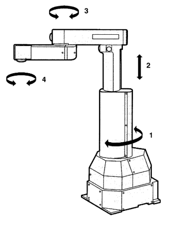
(Fig 2) SCARA Robot Structure
SCARA robots are specifically designed for peg board type assembly and are heavily used in the electronics industry. They’re very stiff in the vertical direction but have a degree of compliance in the horizontal plane. This enables minor errors in the placement of components, which need to be accounted for.
These robots tend to be fairly small and capable of operating very accurately and at high speed. They’re used for assembly, palletisation and machine loading.
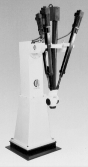
(Fig 3) Tricept Robot
Tricept and hexapod robots use linear motors to control the position of the tool. The tricept uses three of these legs in conjunction with a central pillar to hold the head rigidly in position and then has a standard wrist mounted on it to achieve the orientation. They’re a type of “parallel” robot due to their “closed kinematic chain”.
A hexapod uses six legs and achieves both position and orientation using them. Both structures create very rigid robots, but both have the disadvantage of small working envelopes and limited orientation ability. These structures tend to be used for machining operations where machine tool level tolerances are not required but greater flexibility is.
Cartesian Co-ordinate Robots
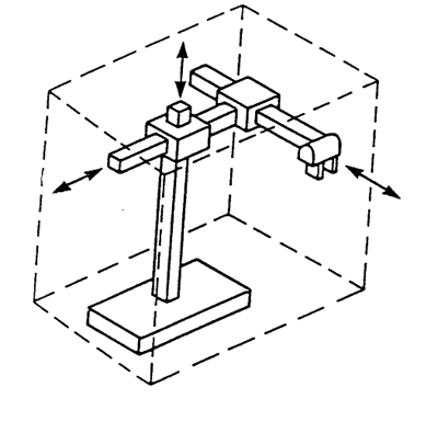
(Fig 4) Cartesian Co-ordinate Robot Structure
This structure is most often seen in machine tools and coordinate measuring machines due to its high rigidity. It produces a robot that is very accurate and repeatable but lacks flexibility as it cannot reach around objects.
These robots are very easy to program and visualise but require a large volume to operate in. They’re mainly used for pick and place operations and operations requiring great accuracy. Their linear joints are difficult to seal, which makes them unsuitable for working in damp and dusty environments.
They come in a vast range of sizes from small ones for picking and placing small parts to ones that span automated production lines, a gantry, carrying large assemblies or even robots dangling downwards to move parts and assemblies from one automated cell to the next.
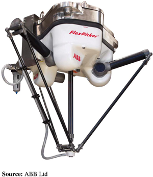
(Fig 5) Delta Robot “FlexPicker” from ABB Ltd [6]
The delta is another parallel robot. Arguably the fastest but with only 4 axes, there are 4 degrees of freedom, so very limited movement. Largely used in the food industry for fast picking and placing applications for lightweight products (e.g. chocolates, biscuits, croissants etc.) as they can only take small payloads of up to 8kg [6].
Therefore, they have to be easy and safe to clean with water. Their electrics are kept out of the way at the top and covered with additional protection during clean down. They can also be used in other end-of-line applications such as picking and packing.
Consisting of one or two jointed arms, a two-arm collaborative robot will typically resemble a human and be a similar size to a large adult. The main design features that distinguish them from a normal industry jointed arm is that they’re designed for safety with soft parts and stop quickly when any collision is detected.
Designed with the intention of working next to humans on a production line without the usual safety precautions, such as physical guarding or light curtains, they enhance your process’ safety. Some have screens as faces.
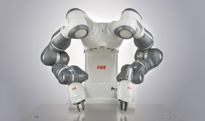
(Fig 6) A collaborative robot with two 7 degree of freedom arms plus cameras made by ABB and called “YuMi”. [7]
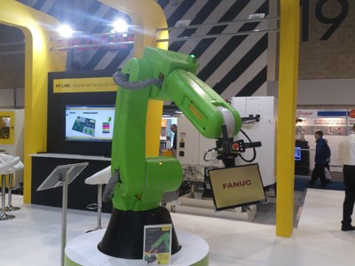
(Fig 7) Single arm collaborative robot by Fanuc.
There are some designs that are no longer manufactured:
This robot consisted of a vertical linear joint, which had a rotary joint angling a radial linear joint. They had good rigidity and were suitable for jobs requiring straight-line moves and reaching into cavities. This made them ideal for machine tending and simple to program as their motion is easy to visualise.
However, they failed to reach around objects and required a large amount of clearance behind them. Their linear joints made them unsuitable for dusty or damp environments.
The first ones to be used in industry as they were ideal for hydraulic drives. They were very fast and accurate robots as the centre of mass was at the centre of rotation of the major joints, giving it a small moment of inertia.
Instability in robots is a key consideration for reliable working and safety. The general approach to instability is to optimise robot arm mechanisms and controls, and to integrate warning systems and alarms. Robots require the highest standards of design, engineering and installation.
For jointed arm or articulated arm robots, the ability to achieve any position and orientation within the working envelope can cause control problems. When driving these robots in their natural co-ordinate system (joint space) the motion of the robot from one point to another can be difficult to visualise, as the robot will move each joint through the minimum angle required.
This means the motion of the tool will not be a straight line. To address the problem, parallelogram structures are introduced to add stiffness and increase the accuracy of movement.
For collaborative robots, problems can arise in the human/robot interface. While technical problems can arise, the main issue for cobots is the training and performance of their operators. Issues need to be addressed in HRI (Human Robot Interface) documentation. Policy makers need to produce and implement standards according to the requirement in each installation.
Autonomous mobile robots (AMRs) are an increasingly familiar feature in warehousing, production and packaging facilities. The danger of collisions is always apparent, but increasingly sophisticated motion sensor and intelligent camera systems are now deployed to minimise risk. At the same time, control systems are now in place which ensure accurate, collision-free movement.
Industrial robot structures are now used in a wide range of sectors including:
Developments for the future include increasing their adaptability and flexibility, achieved through advances in several key disciplines. These include:
For further information about robotics and automation explore BARA – the British Automation and Robot Association.
Sources
6. ABB Robotics, “IRB 360 FlexPicker”, ABB Robotics [Online] Available from: http://new.abb.com/products/robotics/industrial-robots/irb-360 [Accessed 23/4/17]
7. ABB Robotics, “YuMi® - IRB 14000 Collaborative Robot”, 2016, [ONLINE] Available from: http://new.abb.com/products/robotics/industrial-robots/yumi [Accessed12/8/19]